Bearing Capacity of soil
Some of the Terminologies related Soil bearing capacity of soil to be known:
Bearing Capacity of soil: The maximum load per unit area the soil can resists or bear is known as bearing capacity.
Gross Pressure intensity (q): It the total pressure intensity caused due to the load from super structure and over burden pressure (weight of overlying soil).
Net Pressure intensity (qn): q – (γ * D)
Ultimate bearing capacity of soil (qf): The minimum load at which the soil undergoes shear failure.
Net ultimate bearing capacity (qnf): qf – (γ * D)
Safe Bearing capacity (qs): The maximum load at which the soil takes the risk of shear failure is know as safe bearing capacity of soil.
Net safe bearing capacity (qns): qs – (γ * D)
Methods for determining the bearing capacity of soil
There are number of soil bearing capacity test which among the below are the main and important test followed by many years in Civil Engineering.
1. Method of loading for bearing capacity of soil:
 The materials required for the test are as follows:
Steel square plate: The size of the steel square plate usually varies from 3000 to 7500mm2 in area and should have 25mm of minimum thickness.
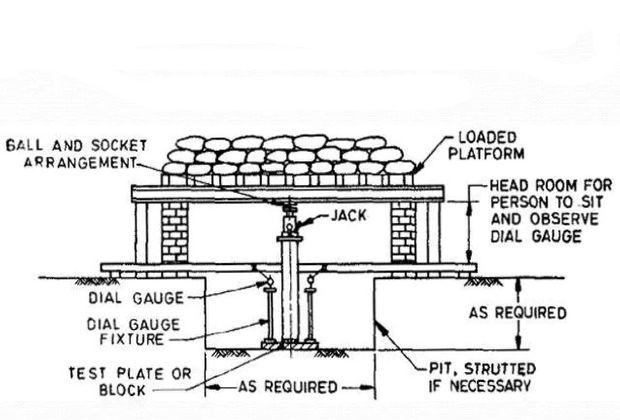
Platform: Platform is usually made of a wooden table having four legs and a plank board at the top of it as shown in the above fig. The two blocks of wooden beams are placed on the plank board in a well-balanced position.
Wooden pegs: These wooden pegs are provided at 50mm projection from ground level which are used to maintain the bench mark.
Dumpy level with staff: This levelling instrument is used to note the settlement of the steel plate.
Rolled steel sections: These available in standard size and weights and they are arranged in two layers over a platform to take the load of sand bags.
Sand bags: They are used for incremental loading.
Procedure
A square pit of required size is excavated up to required depth. The side of the pit is equal to 5 times the side of the steel plate. At the center, a square hole is dug of size equal to side of the steel plate. The bottom of the hole should correspond to the foundation level and the ratio of breadth to depth of pit should made equal to ratio of depth to breadth of hole.
The bottom of the hole is made levelled by scraping and it is well protected against the disturbing forces before and during the test.
The steel plate placed and platform is prepared as shown in fig.
The amount of initial load is decided according to the type of soil to be tested. The weights of steel plates, wooden table and wooden beam should be carefully worked out.
A dumpy level is planted to note the settlement of the steel plate with reference to a permanent bench mark.
The load is to be kept on the platform till the settlement of the ground ceases or stops.
Then the load is increased by a suitable amount, usually by 5KN and the procedure is continued. For this purpose, the weighed sand bags are used.
A graph of load-settlement is plotted.
Bearing capacity of Soil in KN/m2= Maximum Load / area of steel Plate
Safe Bearing capacity of soil in KN/m2= Bearing Capacity of soil /FOS
2. Plate load test:

Plate load test is modern refined method and it is widely used in determining the soil bearing capacity for important civil structures.
Procedure
The test pit and the square hole for the steel plate are made as in the previous method. The plate is firmly seated in the hole. If the ground is slightly uneven, a thin layer of sand is spread below the plate. The loading is done with the help of sand bags, stones or concrete blocks.
The load is applied in convenient increments say about 1/5th of the expected safe bearing capacity or 1/10th of the ultimate bearing capacity
The settlement of the plate is observed by two sensitive dial gauges which are fixed at diametrically opposite ends and supported independently on a suitable datum bar. The sensitivity of the dial gauges should be 0.02mm.
As the plate settles, the ram of the dial gauges moves down and settlement is recorded. The load in indicated on the load gauge of the hydraulic jack. The settlement should be observed for each increment of load after an interval of 1, 4, 10, 20, 40 and 60 min and thereafter at hourly intervals.
The recording of settlement is continued until the rate of settlement becomes less than 0.02mm per hour. The next load increment is then applied. The maximum load that is to be applied corresponds to 1.50 times the estimated ultimate load or 3 times the proposed allowable bearing pressure.
The load-settlement curve is plotted.
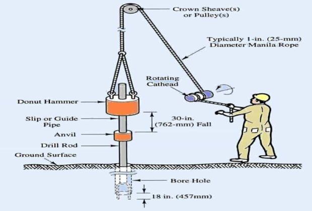
3. Penetration test:

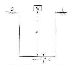
In this method, a substance of known weight is dropped from a known height. The depth of impression made by the weight on the soil is noted. Then bearing capacity of soil is determined as follows

R = resistance of soil
h = height
d = depth of impression
w = weight of the substance
Then Total energy
R * d = w * h
R = w*h/d
A = cross section area of the substance
R/A = resistance of the soil per unit area
Therefore Safe Bearing capacity of soil = R/(A *f)
Where f= factor of safety
Related –What is Soling?| Why it is done? | Types | Procedure
4. Analytical methods:
The analytical methods involving the use of soil parameters like angle of internal friction and cohesion are now available to determine the ultimate bearing capacity of soil.
5. Presumptive values of bearing capacities of soils:
The presumptive value of maximum safe bearing capacity of various soils is now available from codes or other sources which are adopted for designing the foundations for light loaded structures.
Below are the maximum presumptive value of safe bearing capacity of various soils and rocks.
| Types of soil/Rock | Safe Bearing Capacity kN/m2 |
| Rock | 3240 |
| Soft Rock | 440 |
| Coarse Sand | 440 |
| Medium Sand | 245 |
| Fine Sand | 440 |
| Soft Shell/Stiff Clay | 100 |
| Soft Clay | 100 |
| Very Soft Clay | 50 |
Also Read – What is gabion?| Types | Advantages | Applications | Disadvantages

