Pre-stressed concrete methods
The methods of application of pre-compression (pre-stress) to concrete can be broadly classified as below:
1. External Prestressing
2. Internal Prestressing
3. Chemical Prestressing
4. Thermo Electric Prestressing
1. External Prestressing:
 |
| Image source -Google Images
|
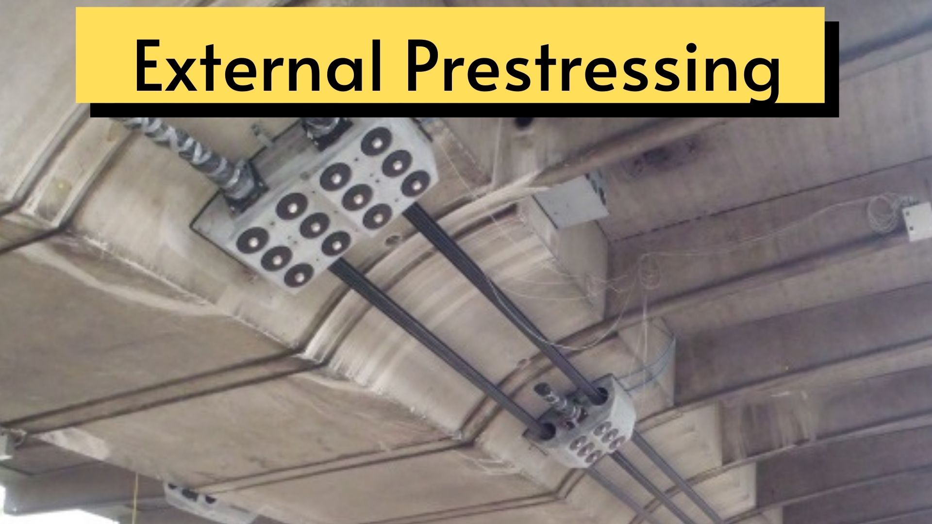
This method involves generation of compressive force between the structural elements and its abutments using flat jacks. A member can be prestressed by external reaction offered by rigid abutments. For a simply supported beam external prestressing can be done by jacking against abutments.
Such an arrangement, however, cannot be easily accomplished in practice as even if abutments favorable for such a layout are obtainable, shrinkage and creep in concrete may completely offset the strains unless they can be readjusted. This type of pre-stressing is probably suited for arch bridges having rigid abutments.
2. Internal Prestressing:
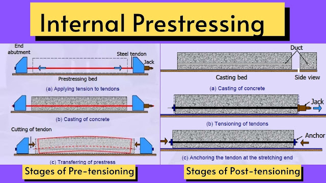
In internal prestressing method, the prestress is provided by tensioning longitudinal high tensile steel embedded in concrete or housed in ducts, accordingly they are called Pre-tensioning and Post-tensioning. This method is most common because greater degree of accuracy can be achieved in execution.
 |
| Image source -Google images |
Pre-Tensioning:
Pre-tensioning is an internal method of prestressing in which the high tensile steel is stretched between two bulkheads in a prestressing bed. Concrete is then cast around the tensioned tendon, in required shape, when the concrete attains sufficient strength, the wires are released, which results in transfer of prestress to the concrete member. Here the force is transferred by bond between steel and concrete.
Post-Tensioning:
In post tensioning, firstly the structural elements are cast with longitudinal ducts for prestressing tendons to run through. The ducts are provided with metal sheathing placed in proper position and they are called cable ducts.
The prestressing steel tendons are inserted through cable ducts later. After the concrete attains the required strength, the prestressing steel tendons are pulled against the concrete element and anchored at the ends by means of special type of patented external anchorage systems. The force is transmitted through external anchorage system at the ends of the structural concrete element.
3. Chemical Prestressing:
In this method prestressing of concrete is made possible by using expansive cements. Since the expansion of concrete made using expansive cement is restrained by high tensile steel wires, compressive stresses develop in concrete and tensile stresses in steel. With this method called self stressing method, limited compression can be imparted to concrete.
4. Thermo Electric Pre-stressing:
The method of prestressing by heated tendons, achieved by passing an electric current in the high tensile wires, is called Thermo Electric Prestressing. By this process it is possible to induce initial stress of upto 500 to 600 MPa in the steel.
Also Read: What is Prestressed Concrete? Advantages & Disadvantages | Applications
Different Types of prestressed concrete system
1. Freyssinet System :
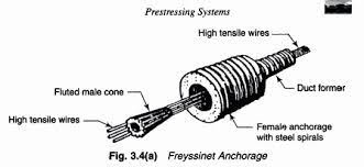
The method, developed by French engineer Freyssinet is one of the most widely used method of prestressing and is based on wedge action of anchorage. The system consists of two parts. (i)the female cone, (ii)the male cone. The female cone is a precast RCC cylinder having corrugations on the outside, conical hole in the center and a heavy hoop reinforcement. The male cone is a precast RCC conical plug, cast around a steel tube as shown in figure, the male cone has longitudinal groves numbering from 8, 12 or 16 on its surface so that the high tensile wires (5mm or 7mm in dia) rest in these grooves while tensioning.
 |
| image source – google images |
The female cones are placed in position at each end of the beam. When concrete is placed in the formwork, the female cones get embedded in the concrete and on account of their corrugated outer surface they get well bonded with the concrete when the member is cured and hardened. After the concrete sets and attains required strength, the tendons are tensioned by using Freyssinet jacking unit wires or tendons of cable are passed through the grooves of male cone. These wires are gripped by the wedges on the main piston of the jack.
2. Magnel Blaton System :
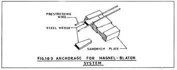
In this system, the anchorage consists of steel plates called sandwich plates with two trapezoidal grooves in the upper surface and two in the lower. Each groove can hold two wires and the wires are held in position by a steel wedge, which fits in the slot. Thus, in a sandwich plate 8 wires can be anchored and a cable anchorage system may be built up of a number of such plates, laid one over the other.
 |
| Image source -google images |
With the help of tensioning device wires are tensioned one at a time. The sandwich plates are placed in the form of bank one above the other against a distribution plate and held thus by means of a temporary bolted clamp during tensioning operations. For stressing the wires hydraulically operated stressing jacks are used with arrangement of holding two wires at a time.
When the wires have been tensioned to the desired limit, the steel wedge is derived home inside the groove which holds the two wires firmly in position. Thus the anchorage assembly transfers the prestressing force to the precise concrete members through the cast steel distribution plate interposed between the anchorage assembly and the end face of the member at each end. Thus sandwich plates extend beyond the end of the concrete as shown in fig. when the stressing in completed, it is invariably grouted and the anchorage is covered with concrete for protection.
Advantage of Magnel Blaton System
1.The cables are stressed uniformly as two wires are stretched at a time.
Disadvantage of Magnel Blaton System
1.It takes more time than Freyssinet system and sandwich plates extend beyond the end of the concrete.
3. Gifford Udall System :
The Gifford-Udall (C.C.L) system developed in U.K. consists of steel split-cone and cylindrical female-cone anchorages to house the high-tensile wires bearing against steel plates. Each wire is tensioned separately and anchored by forcing a sleeve wedge into a cylindrical grip resting against a bearing plate. The ducts are generally formed by metal sheaths cast into the concrete member.
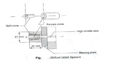
The cable consists of parallel wires of 7mm dia. The cables are separated by means of circular spacers placed about a meter apart. The first and last spacer lie at about 50cm from ends. Toprevent the spacers to shift their positions, the cable is tied by a thin wire all-round behind each spacer.
There are two types of Gifford Udall anchorage systems
a) Plate anchorage b) Tube anchorage
4. Hoyers’s long line system :
Hoyer’s system is used for mass production of pre-tensioned members. It is also called long line method.

The Hoyer system consists in stretching the wires between bulkheads several meters apart (100 to 150m) The bulkheads can be anchored to the ground independently or they can be connected by along stressing bed.
The wires are stretched by hydraulic jacks. The concrete is then poured so that a number of beams can be produced in one line. After the concrete has hardened the wires are released from the bulkheads. The wires between the different units in one line of beams will also be cutoff. The prestress is transferred to the concrete through bond between the tendon and the concrete.
Examples of Hoyer’s long-line method of pre-tensioning: Railway sleepers, Electric poles, lintels, floor beams.
Advantages of Hoyer system :
1. It is suitable for mass production of small members.
2. Rigid quality control under factory conditions can be ensured.
Also Read: types of footing used in construction
